Vallecito Dam Construction Project
Pages
-
-
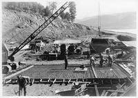
Placing spillway floor panel (1)
-
Placing concrete in floor panel at left side of spillway inlet structure, stations 5+29.89 to 5+57.50. Looking upstream in spillway from spillway crest., Original photo number: Pine R - 360
-
-
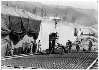
Placing spillway floor panel (2)
-
Placing spillway floor panel at left side, sta. 9+70 to 10+05. Gentleman in dark suit (second from left) is A. E. Kelso, Engineer of Water Supply for Melbourne and Metropolitan Board of Works, Victoria, Australia, who was visiting the project., Original photo number: Pine R - 342
-
-
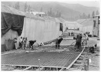
Placing spillway floor panel (3)
-
Placing spillway floor panel at left side, station 9+70 to 10+05. Note adjustable, curved template being used to shape surface of concrete., Original photo number: Pine R - 373
-
-
Placing spillway floor panel (4)
-
Placing concrete in floor of spillway at right side between stations 11+44 and 11+78. Note adjustable curved template in foreground used to shape surface of concrete., Original photo number: Pine R - 374
-
-
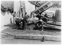
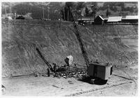
Placing spillway wall footing
-
Placing spillway wall footing on left side of channel at station 12+00. Concrete is hauled to dragline bucket in dump trucks., Original photo number: Pine R - 079
-
-
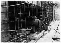
Radial gate hinge pin anchor
-
Radial gate hinge pin anchor in place on right spillway wall. Note pin bearing aligning device. Wooden blocks under anchor were replaced with steel supports before concrete was placed., Original photo number: Pine R - 403
-
-
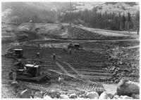
Raking oversize cobbles
-
Raking oversize cobbles (over 5" dia.) from No. 3 material on embankment. Oversize is pushed into cobble fill section. Refer to Pine R - 244., Original photo number: Pine R - 350
-
-
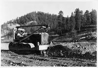
Removing stones from diversion channel embankment
-
Removing plus 5-inch stones from No. 3 zone of embankment in the diversion channel, using rock-rakes and hand-pickers. Looking toward left abutment from station 24+30, 175 ft. downstream from axis., Original photo number: Pine R - 439
Pages